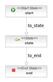
Process modelling
We are going to describe the elements which define a jBPM process. A process is composed by:
- Nodes
- Transitions
To create a process definition in a graphical way, you can use jBPM Graphical Process Designer. This tool is packaged as a Eclipse plugin.
Nodes
The define the states of the process definition. They are connected by transitions. Both define the different path which can be followed in a running process definition. A running process definition is called process instance.
There are several types of nodes:
Start node
The start node defined the process entry point. Only one start node is permitted.
End node
End nodes define the end of the process execution. A process may have several end nodes. In this case the process finish when the process arrives to any of these end nodes.
Task node
Node node
You can define the behaviour using a Action element, which will be executed when the process arrives to the node.
State node
Decision node
There are 2 ways to model a decision. The distinction between the two is based on *who* is making the decision.
- When the decision is to be taken by the process, a decision node should be used.
- When the decision is taken by an external party, you should use multiple transitions leaving a state.
Fork node
A fork node splits one path of execution into multiple concurrent paths of execution.
Join node
The join node take all these concurrent executions before continue with the process execution.

